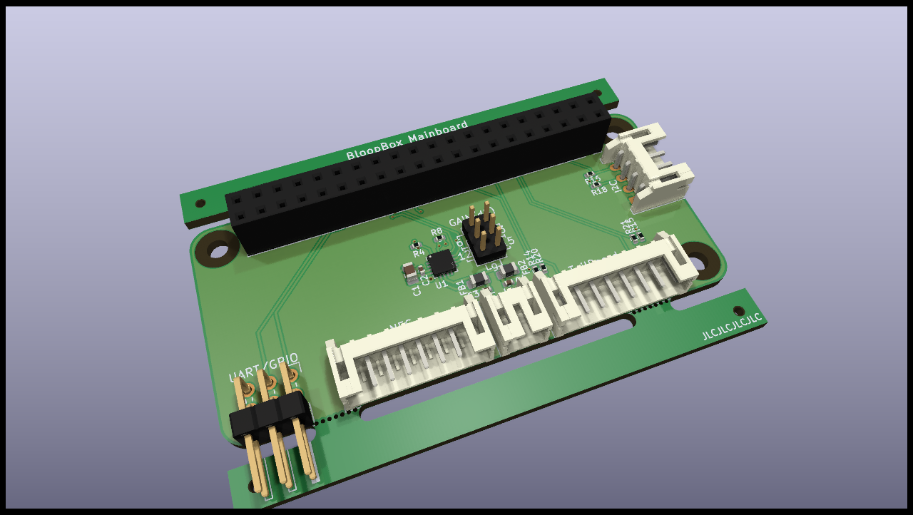
The board is designed using KiCAD 6 with production and assembly by JLCPCB in mind. All parts are selected to be available from JLCPCB at the time of writing and as many parts as possible are used from their basic library.
- uHAT format (fits on a Raspberry Pi Zero)
- Connectors for:
- Tailboard (Power supply, buttons, LEDs)
- SPI NFC-reader (Pinout fitting for RC522 Module)
- Speaker
- I2C connector for LED-Board
- Additional GPIO header with UART (optional)
- Speaker is driven by a MAX98357 3W amplifier
- amplifier gain can be set through jumper (9dB default setting)
- SD_MODE is set to stereo mix by default, solder jumper for setting left-only
Pinout of all connectors is printed on the bottom of the board
See schematics for detailed GPIO pinout
