So this is a simple clock with a character LCD display, RTC module, and a ESP8266 in role of microcontroller. I choose an ESP8266 cause later I want to create NTP version of this clock, so You dont need to buy a RTC module, cause clock will get time info via Your WIFI network. In order to display hours, minutes, and seconds - You need LCD display that contain 20 columns and 2 rows. Each digits occupies 3 columns on each row. So in clock we have 6 digits, 6*3 = 18, and we have 2 columns left, which we can use for a separator dots. You still can use 16x2 display, but in this case You need to slightly modify code, so seconds wont display.
- Easy to set up
- Big cool digits
- Minimalism, nothing unnecessary
- Adjustable brightness. Backlight will dim at night, so clock wont blind you
- ESP8266
- 20x2 Character LCD Display
- DS1307 or other compatible RTC with I2C
- 2N2222 or similar NPN bipolar transistor
- 1K resistor
- 10K adjustable resistor
- Bunch of wires
Here is a schematic:
Schematic may be vary according to what microcontroller, RTC, or display You are using. I used 4 bit data bus on display, but thats okay if You use I2C module for display, You will just need to change display initialization(and maybe display library). Display backlight is controlled via 2N2222 transistor, with PWM.
rs, en, d4, d5, d6, d7 - is a GPIO pins connected to display.
pwm - GPIO pin that connected to a transistor.
backlightDimStartHour and backlightDimEndHour - as the name suggest, contains hours interval, when display backlight will be dimmed.
backlightDayLevel and backlightNightLevel - define how bright backlight will be at day, and how dimmed it will be at night. Its a default PWM range, so int is suitable in range 0 - 255.
pwmFreq - Frequency of PWM that will control backlight. Default value is 1 kHz, but I changed it to 40 kHz cause in 1 kHz high frequency squeal was heared from my display.
To work properly, You need to install next libraries:
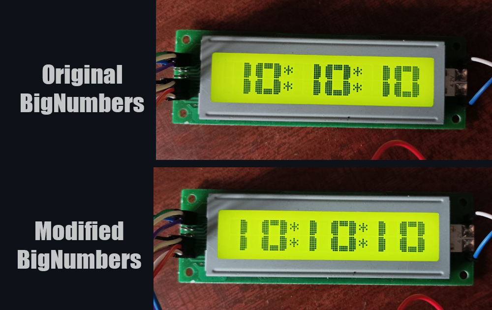
BigNumbers, as You can see, main library in this project. Very cool library by seanauff. I slightly modified it, how its draws digits "1". You can see comparison below. You can download original library by link above, or use modified one, all libraries, including modified "BigNumbers" are located in folder "libraries" in this project. Still, if You want modified one, anyway go and support original work of seanauff.
After You connected all according to schematic, you need to upload firmware to ESP8266, twice. When You do it first time - just upload code from project. When its second time, You need to comment line that responsible for time/date adjustment in RTC module. From this
rtc.adjust(DateTime(F(__DATE__), F(__TIME__)));To this
//rtc.adjust(DateTime(F(__DATE__), F(__TIME__)));If You wont do it, it may cause some problems in future, every time when clock will turn on, it will readjust RTC module with time and data that was on the moment you upload firmware into Your ESP8266.


