This repository contains C++ code for implementation of Model Predictive Controller. MPC is used to derive throttle, brake and steering angle actuators for a car to drive around a circular track. This task was implemented to partially fulfill Term-II goals of Udacity's self driving car nanodegree program.
A critical module in the working of any robotic system is the control module. Control module defines the action, which the robotic system performs in order to achieve a task. These actions can vary on type of the system and type of the task. For e.g.: A simple mixer grinder's control module only controls the speed of rotating motor. A little more complex system such as a Remote Controlled (RC) car needs a control module to move forward, backward and turn. Highly complex systems such as prosthetic arms, self driving cars, product manufacturing factory units require control modules for multiple tasks at the same time.
One of the basic implementation of a control system is a Proportional (P), Differential (D), Integral (I), together, a PID controller. PID controller is the most popular controller and is used in applications across domains. But PID controller cannot be used for controlling complex systems such as self-driving vehicles as one needs to guarantee a smooth and safe journey and not just navigation from one point to another.
A more sophisticated class of controllers is the Model Predictive Controller (MPC). MPC is built taking into consideration the motion model of the system. Hence, this controller adapts to any sort of secondary ask along with the primary ask. For e.g., as mentioned earlier, MPC can be used not only to perform the primary task of navigation but also to ensure a smooth ride of a self-driving vehicle. This is possible as one can start with a simple motion model and then easily add new parameters to the cost function. Also, being more sophisticated, MPC can also be used to model different uncertainties and external environmental factors into the motion model of the system.
MPC is a non-linear system which generates optimized parameters with the constraint of obtaining minimal value of cost function. Here, cost function refers to the problem built by taking into consideration the model of the system, range of inputs, limitations on outputs and/or the effect of external factors acting on the system.
A typical cost function in case of a self-driving vehicle will have following constraints:
- The cross track error (cte), i.e. the distance of vehicle from the center of the lane must be minimal.
- The heading direction of the vehicle must be close to perpendicular to the lane. Error PSI (epsi) is the error in heading direction
- Oscillations while riding the vehicle must be minimal, or one would feel sea sick. This takes into account the change in heading direction due to turns and also the change in speed due to acceleration/braking.
- The vehicle must drive safely and should not exceed the speed limit. In contrast, the vehicle must also not drive too slow as one wouldn't reach any place.
These constraints are merged to form a cost function. MPC tries to reduce the cost function and come up with the values of actuation inputs to the vehicle, which can be the steering angle of the wheel and/or the throttle/brake magnitude.
In this project, MPC was implemented to drive a car around a circular track having sharp left and right turns. A good solution would help the car stay in the center portion of the lane and take smooth left and right turns without touching or running over the edges of the lane (considered as risky in case humans were travelling in such a car). Also, the final implementation had to be tested with speeds as high as 100mph and note down the behavior of the car.
Simulation of a circular track was achieved in the Udacity's self driving car simulator. While MPC was implmented in C++, the simulator communicated to C++ code with the help of uWebSockets library. Following parameters were received from the simulator for each communication ping:
-
List of waypoints with x and y coordinates of each point in global map system. These waypoints represent the suggested trajectory for the car from current position to few distance ahead of it. Such type of information is usually received from a Path Planning Module implemented in self-driving vehicles. The path planning module generates reference trajectory for a section of the total journey based on the current location of the vehicle.
-
The current position and heading of car in global map system.
-
The current steering angle and throttle applied to the car.
-
The current speed of the car.
More technical details on the parameters received from the simulator can be found in the DATA File
The final implementation consisted of following major steps:
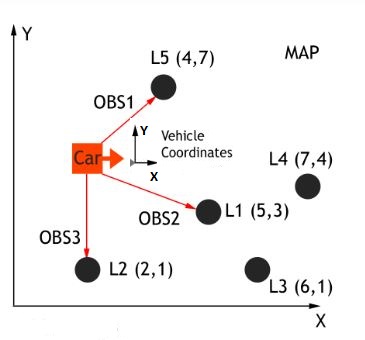
In this step, the coordinates of waypoints were transformed from global map system to vehicle's coordinate system. This was done to ensure the calculations of cte and epsi were less complex and involved less calculations. An overview of global map coordinate system and local vehicle system coordinate system is shown below:
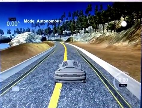
The transformed coordinates of waypoints were then used to create a smooth curved trajectory, which will act as a reference for motion of the car. This is done by using polynomial fitting or regression technique. In this technique, discrete points are fitted to a polynomial of desired degree in order to obtain the relation function between x and y coordinates, also known as the curve equation. In this project, the waypoints coordinates were fitted to a 3rd degree polynomial. A smooth curve was drawn inside the scene in the simulator shown by yellow line in the screen cap below:
As a result of transformation of data in step 1, the calculation of cte was a linear function and the calculation of epsi involved taking arctangent of the first order coefficient of fitting polynomial. The formulae are given below:
In this step of initialization, the second terms in the formula turn to be zero. In the later time steps, second term came into consideration.
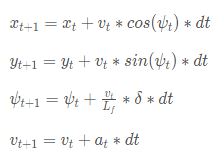
The motion model in this project was based on the Kinematic equations of motion in 2 dimensions.
The state consists of following parameters: 1. The x coordinate of position of car in vehicle's coordinate system (x) 2. The y coordinate of position of car in vehicle's coordinate system (y) 3. The heading direction of car in vehicle's coordinate system (psi) 4. The magnitude of velocity of car (v)
The actuator inputs used to control the car are given below: 1. The magnitude of steering (delta). This was limited to [-25, 25] as per the angle specification of simulator. 2. The magnitude of throttle (a). This was limited to [-1, 1] as per the throttle/brake specification of simulator.
The state update equations are then given by:
Given the reference trajectory from polynomial fit of waypoints and the motion model of the car, MPC estimates the value of actuator inputs for current time step and few time steps later. This estimate is used to predict the actuator inputs to the car ahead of time. This process of estimate generation is tunable with the use of N and dt. Higher value of N ensures more number of estimates while higher value of dt ensures the estimates are closer in time. Different combinations of values of N and dt were tried and following were the obervations:
    N and dt            Observation/Effect

    N = 10, dt = 0.1	  Sharp turns as less number of discrete points between subsequent states
    N = 20, dt = 0.1	  Estimate too ahead of time resulting in slower implementation of algorithm
    N = 10, dt = 0.05	  Too close estimates resulting in oscillation of car at slow speeds
    N = 7, dt = 0.07	  Perfect combination for motion of car
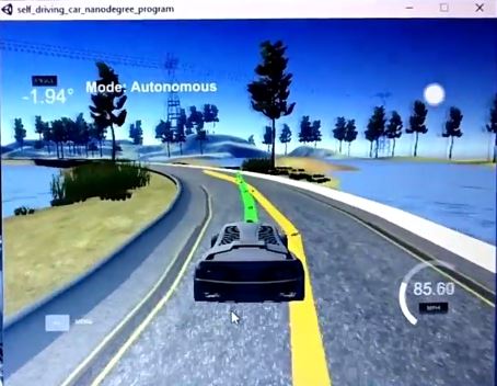
After trial and error, a setting of N = 7 and dt = 0.07 (sec) was used to predict actuator inputs and the trajectory of car for roughly next 500ms. MPC implementation generates the coordinates and heading of car for next 500ms and is drawn inside the simulator using green curve as shown below:
In order to define the cost function of the system, it was essential to list down the desired values of different parameters. They are given below:
- Expected value of CTE to be zero
- Expect value of EPSI to be zero
- Maximum speed of the car to be 100mph. This was a tunable parameter and the goal was to test the maximum speed at which the car stays on the track and moves safely.
The last step in the implementation is to define the cost function for MPC. MPC solver, implemented using [Ipopt]((https://projects.coin-or.org/Ipopt) and [Cppad]((https://www.coin-or.org/CppAD/) library generated actuator values while arriving at the minimal value of cost function. Key elements and features of the cost function are given below:
- Highest weight for calculated CTE and EPSI. This was to ensure the car stays in the middle of lane and head in desired direction
- Reduce high initial values of control inputs (delta and a) to ensure there is no jerk in motion of the car
- Minimize the change in values of control inputs (delta and a) in order to minimize oscillations in the motion
- Minimize speeds at higher steering angle and minimize steering at higher speeds. This was to ensure the car took smooth turns by reducing the speed while it reached maximum possible speed on straight ahead path
In real world systems as complex as commercial jet planes, there exists certain amount of delay in time between the actuation of control and its effect on the motion. To achieve an implementation close to real world scenario, a latency of 100ms was introduced in the simulator. This delay caused control actuations to reach the car in later of time. This worked fine at low speeds till 25mph but resulted in undesired behavior at high speeds. To take into account the effect of this latency, the state parameters for next state were calculated beforehand and were sent to MPC for generating steering and throttle values. This ensured the actuations applied at current point of time were actually for the next time step (i.e. after 100 ms). This small update in state calculation solved the problem of latency and the car was back on track w.r.t. its desired behavior.
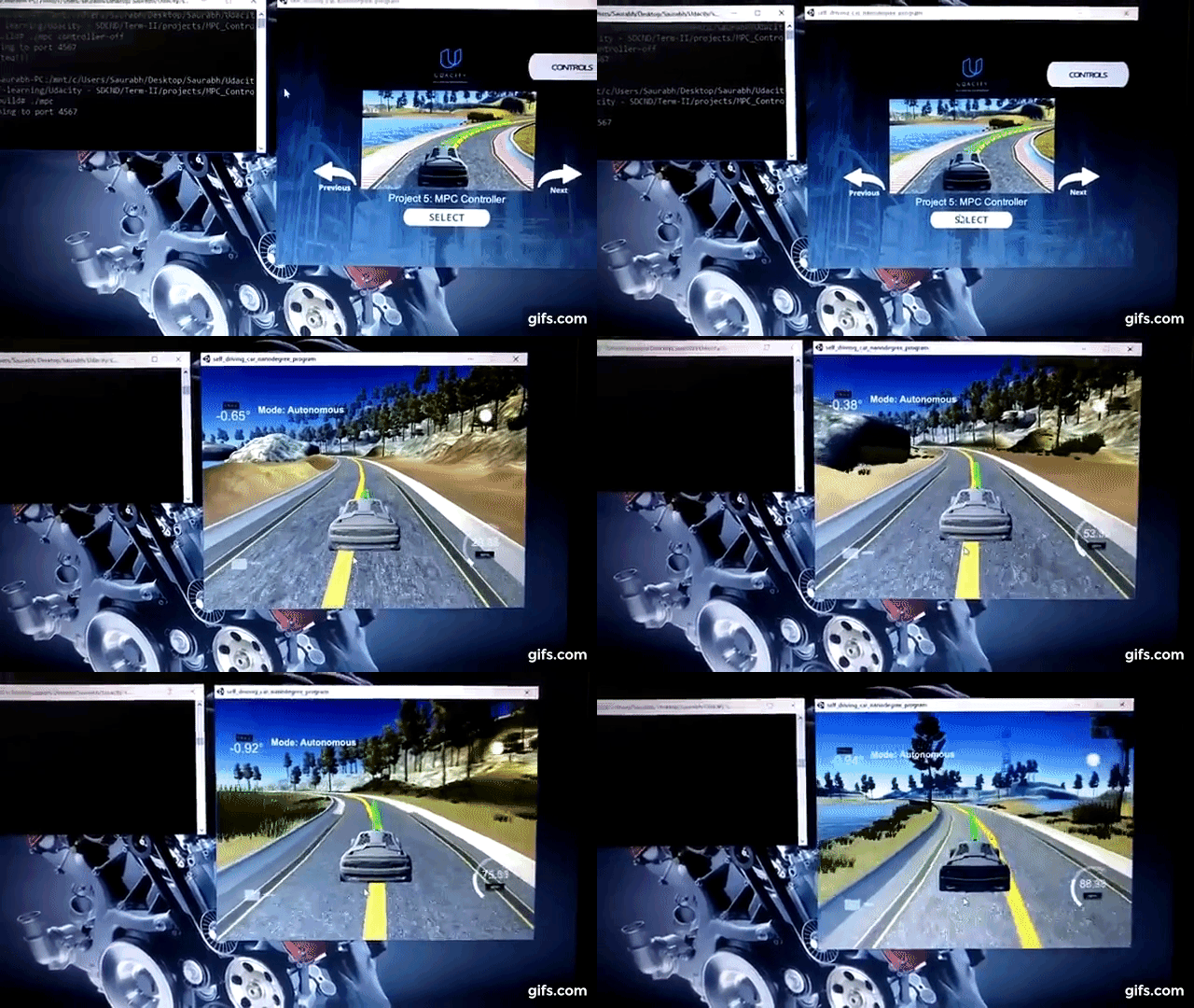
MPC used to derive the steering angles and throttle/brake for a car moving on a circular track was implemented successfully. The car could stay close to the center of the lane and take smooth left and right turns along its path while reaching speeds as high as 97mph. This was achieved in spite of presence of latency in the system. This is demonstrated below:
Detailed insight into features of the simulator and implementation is demonstrated in this MPC demo video.
-
cmake >= 3.5
-
All OSes: click here for installation instructions
-
Linux and Mac OS, you can also skip to installation of uWebSockets as it installs it as a dependency.
-
make >= 4.1(mac, Linux), 3.81(Windows)
- Linux: make is installed by default on most Linux distros
- Mac: install Xcode command line tools to get make
- Windows: Click here for installation instructions
- Linux and Mac OS, you can also skip to installation of uWebSockets as it installs it as a dependency.
-
gcc/g++ >= 5.4
- Linux: gcc / g++ is installed by default on most Linux distros
- Mac: same deal as make - [install Xcode command line tools]((https://developer.apple.com/xcode/features/)
- Windows: recommend using MinGW
- Linux and Mac OS, you can also skip to installation of uWebSockets as it installs it as a dependency.
-
- Run either
install-mac.shorinstall-ubuntu.sh. This will install cmake, make gcc/g++ too. - If you install from source, checkout to commit
e94b6e1, i.e.Some function signatures have changed in v0.14.x.git clone https://github.com/uWebSockets/uWebSockets cd uWebSockets git checkout e94b6e1
- Run either
-
Fortran Compiler
- Mac:
brew install gcc(might not be required) - Linux:
sudo apt-get install gfortran. Additionally you have also have to install gcc and g++,sudo apt-get install gcc g++. Look in this Dockerfile for more info.
- Mac:
-
- If challenges to installation are encountered (install script fails). Please review this thread for tips on installing Ipopt.
- Mac:
brew install ipopt - Linux
- You will need a version of Ipopt 3.12.1 or higher. The version available through
apt-getis 3.11.x. If you can get that version to work great but if not there's a scriptinstall_ipopt.shthat will install Ipopt. You just need to download the source from the Ipopt releases page. - Then call
install_ipopt.shwith the source directory as the first argument, ex:sudo bash install_ipopt.sh Ipopt-3.12.1.
- You will need a version of Ipopt 3.12.1 or higher. The version available through
- Windows: If you can use the Linux subsystem and follow the Linux instructions or use Docker environment.
-
- Mac:
brew install cppad - Linux
sudo apt-get install cppador equivalent. - Windows: If you can use the Linux subsystem and follow the Linux instructions or use Docker environment.
- Mac:
-
Simulator. You can download these from the Udacity simulator releases tab.
-
Check the dependencies section for installation of gcc, g++, cmake, make, uWebsocketIO API, CppAd and Ipopt library.
-
Manually build the project and run using: a. mkdir build && cd build b. cmake .. c. make d. ./mpc
-
Run the Udacity simulator and check the results
